Engine Timing Calculator
The engine timing calculator is an online tool for determining the exhaust timing, the transfer port timing, and the exhaust timing advance. The engine timing calculator takes into account the actual piston position.
Note: decimal places must be separated by a period.
Determining Engine Timing
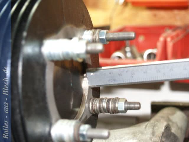
Piston Position
To determine the engine timing, the piston position must be measured.
Transfer Port Timing in Degrees (°)
The transfer port timing describes the period during which fuel from the crankcase can enter the combustion chamber of the cylinder through the transfer ports.
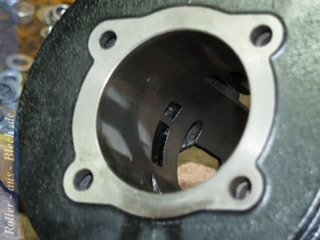
Channel design in a DR 177 cylinder
Transfer ports in a DR 177
Measuring the piston position is important for every tuning. The size of the resulting squish band is crucial for the durability and performance of a Vespa engine. The smaller the squish band, the higher the compression. High compression provides more power, especially at low engine speeds. A too small squish band results in high thermal stress.
Exhaust Timing in Degrees (°)
The exhaust timing describes the period during which fuel exits the combustion chamber through the exhaust port into the exhaust system.
In addition to the exhaust timing, the shape and width of the exhaust port are also crucial.
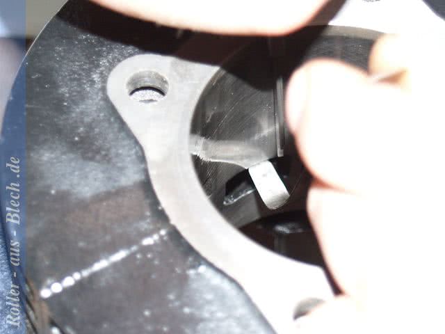
Calculate Exhaust Port Width
The width and shape of the exhaust port are crucial factors for the engine performance and power delivery of a two-stroke engine. Using internal calipers, the Chord length is taken and related to the cylinder bore. The result of this calculation represents the exhaust width as a percentage. In general: the larger the exhaust port, the more peak power is possible, but the higher the stress on the piston rings.
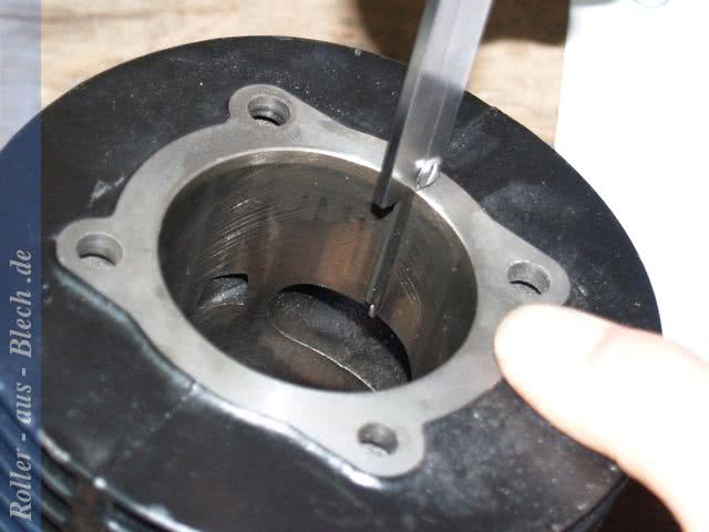
To calculate the exhaust port width, a port map can be used instead of calipers.
The values read with a ruler correspond to the bore measurement, which is converted to the chord measurement using the following calculation.